Colt Boost Tuning 101 – Reprint from Law’s DIY Blog
 Laws DIY Adventures
Mitsubishi Colt Ralliart and CZT Boost Tuning 101
A reprint from Law’s DIY Blog
The following writeup was taken from a now deleted blog 'Laws DIY Adventures', detailing how to work with the reactive boost system on Mitsubishi Colt Ralliart and CZT models. Law - if you come across this and mind my reprint please reach out. Have added to here so I don't lose it and I think it's a great help to many others. Here it is in it's unedited original form:
Doing things the hard *fun* way
Righteo, for the last few years I’ve been mainly covering minor suspension modifications but its finally time to start on increasing power output. First on the list is boost tuning, there’s a huge amount of information on this topic for Evo’s of all generations and Lancer Ralliarts but for the Ralliart colt…. There isn’t much at all. So I figured I’ll put together something for my own reference and for anyone that wants to give it a go.
Disclaimer: I am not a tuner, I don’t claim to be. I don’t have an engineering background of any sort. I’m just a keen individual interested in DIY who seeks to better understand things. With that said, I wont be responsible for any damage what soever caused by following this guide.
Items you need before getting started
- Tactrix Openport 2.0 (No reflash adaptors needed).
- ECUFlash.
- Evoscan
- Ralliart Colt AUS ECU definitions.
- 3Port solenoid of your choosing (A GM 3 port has been used for this guide, but it will be almost the same for any others e.g. Grimmspeed, Tactrix, Perrin, Cobb, MAC … )
- Boost Gauge (Again essential but if you dont have it, follow below warnings).
- Wideband (Quite essential but if you dont have it, follow below warnings).
Software Setup
- Purchase Evoscan (its a small cost and a great tool which will become invaluable during tuning).
- Download megalogviewerHD, great tool to aid in visualization of logged data.
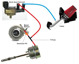
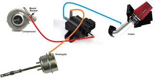
2. Now you need to install a 3 port in the following configuration. You can choose to keep 1 restrictor pill on the compressor > Solenoid line if you wish however keep in mind the addition of a restrictor pill will change the WGDC settings later on. The 3port has been setup in a Interrupt configuration where the wastegate sees no pressure unless the ECU says so. NOTE: Please check the manual on the solenoid you are using to determine what each port does.
What tables are involved (That I know of)
Now that you have completed the above (from a hardware and software perspective you are all good to go). Before starting however, I would strongly recommend spending some time reading up on Merlins Evo X Tuning guide (Evo VII/VIII) one is okay as well. Just to give yourself some background and understanding.
Disclaimer 2: The following focuses purely on the aspects of how to tune boost, you must take into consideration other factors such as ignition timing, AFR’s, MIVEC, Limiters etc etc. It would be extremely unwise to just alter the following boost maps without consideration of any of the above.
Tables that you need to be aware of are shown below with brief explanations. Note table names are taking from the Merlin definitions so may not be 100% correct.
Setup tables
You should only really need to set these up once at the beginning and once at the end, unless you run into issues or would like to fine tune things further.
Descriptions below from left to right.
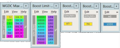
WGDC MAX vs Coolant temp
This table seems to have a direct impact to WGDC when modified, however I dont believe it has been labelled correctly in regards to coolant temp. Would need someone more cluey and in tune with the dev side of things to look further into this. Advice is to leave it alone and tune within the stock parameters.
Boost Limit
Pretty self explanatory, the load limits allowed at each RPM interval. Exceed this figure in combination with the Boost cut delay timer and you will hit limp mode. This is a key safety table and should be adjusted accordingly.
Boost Crossover RPM/MPH # 2 and #3
Used to control at which point the maps switch from Boost Target Engine Load Low/High and WGDC 1 and 2. Best left alone, there is no need to change this.
Boost Cut Delay Timer
The amount of time in ms before boost cut is enforced.
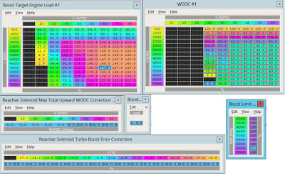
Correction Tables
Once the above is setup, the next lot of tables to look at are the correction tables. These tables will actively add/subtract WGDC based on error %’s and TPS to try match the prescribed boost load targets.
Descriptions from left to right (top down)
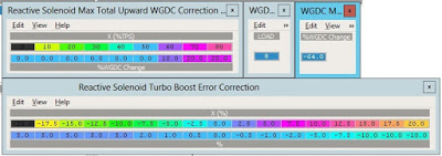
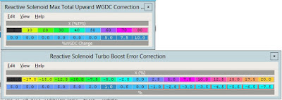
Reactive Solenoid Max Total Upward WGDC Correction vs TPS
Max WGDC upward corrections based on TPS%
WGDC Correction Interval
Defines what interval the ECU will sample boost at for active corrections.
WGDC Max Total Downward Correction
Defines the max allowable downward WGDC correction.
Reactive Solenoid Turbo Boost Error Correction
The key correction table which dynamically adjusts load based on error %.
Target Loads and WGDC Tables
These set of tables directly control the boost targets you are trying to reach and the WGDC settings required to get there.
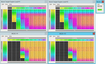
Boost Target Loads, WGDC and Boost offset
Boost Target Engine Load #1 LOW
3D table used in conjunction with Boost offset to determine target load in the lower gears as defined by the crossover maps.
WGDC #1
3D table used in conjunction with the Boost target engine load #1 table to control boost in the lower gears as defined by the crossover maps.
Boost Target Engine Load #2 HIGH
3D table used in conjunction with Boost offset to determine target load in the higher gears as defined by the crossover maps.
WGDC #2
3D table used in conjunction with the Boost target engine load #2 table to control boost in the higher gears as defined by the crossover maps.
That is it for this post, aim was to simply go over the setup items and familiarise yourself with how ECU boost control works, the next post will cover the actual tuning.
—-
After going through the previous post, we should be in a position where everything is set-up and ready to go, Moving on to tuning.
Now that we hopefully understand all the tables involved we can start tune our boost. This section will only cover the base settings and strategy needed to get you going. I wont be including any finalised maps as each car is different and even the slightest differences in modifications will affect boost control dramatically.
Disclaimer: I am not a tuner, I don’t claim to be. I don’t have an engineering background of any sort. I’m just a keen individual interested in DIY who seeks to better understand things. With that said, I wont be responsible for any damage what soever caused by following this guide.
Where do I put in the PSI I want to hit?
There is no such thing, the boost control and entire ECU on the colt reads in LOAD. Merlin has put together a rough table on what load corresponds to what PSI for an Evo. Do not follow this blindly to set target loads, I have found through my own testing though that 160-180 loads roughly line up to the ranges shown in the table but this is not concrete.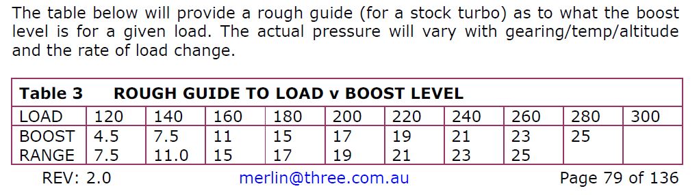
Disclaimer: A few things to consider before we get into it.
- Never set WGDC to more than 40% on either table #1 or #2 when starting to tune (with or without a pill, this is a safe number to start on and will ensure you have yourself a safe baseline to work from.
- As the stock turbo is tiny, WGDC changes in the 2000-2500rpm are especially sensitive. Take extra precaution when adjusting WGDC in these areas as they are normally the key cells which trigger overboost and boost cuts.
- Ensure you remember that Target loads + Boost offset determines the final load you are trying to hit. e.g. 150 target load + 20 offset = 170 final target load*.
- Ensure the Boost limit has been raised accordingly prior to tuning, aka if we are trying to target 15psi which is very roughly ~170ish load, hence Boost limit should be raised to 190 as a start incase of overboost.
- Never lean out AFR’s without a Wideband and especially not during boost tuning. You will find that the stock AFR’s are fairly rich from stock and dip into the 10’s on higher loads, this will be fine for establishing a baseline boost curve. HOWEVER , if during runs knock is detected. Ensure the culprit cells are checked and consider the AFR as well as ignition timing before continuing.
- Always always watch for knock, the stock map is knock prone across the whole spectrum. For the purposes of this guide we are especially interested in knocks above 100 load which we consider to be the transition into positive boost pressure. Any knocks found whilst on boost should be treated seriously especially if it is repeatable.
- I follow the rule in which any knocks greater than 3 AND repeatable must be taken care of. Sporadic 1 or 2 counts are fine by my standards but any successive repeatable chain knocks must be addressed.
Boost tuning strategy
Step 1 – Setting a baseline.
Baseline settings (only shown for low maps, do the same for high)
Step 2 – Do a few runs and log the results.
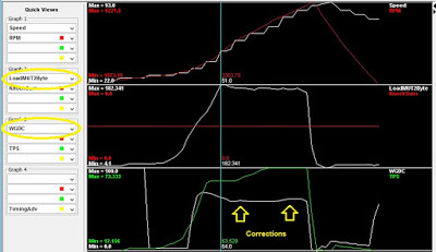
Step 3 – Stepping up WGDC slowly to reach our desired loads.
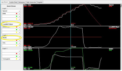
A few runs in, look at the WHITE lines in the middle and bottom charts.
NOTE: this run is done in 2nd gear, same concept applies for higher gears.
Step 4 – Repeating above for both high and low gears
Step 5 – Switch reactive corrections back on
Corrections back on but at a reduced setting.
Step 5 – Fine tuning post corrections
Finished boost curve with corrections on.
Wrap up and things to consider

Leave a comment